Rev B1 ECN-02 — Enclosure mounting (draft)
Draft — EverTag Station only
Proposed mechanical change for the Connectivity Module (232200–232204) and LTE extension (232210). Not approved. Current PCB revision is A2. Does not apply to Tag (230220).
Ships in the same B1 respin as Rev B1 ECN-01 — GPIO remap.
Dimension update (2026-06-09)
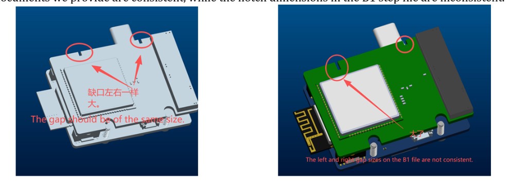
Enclosure-supplier review of the Rev B1 STEP exports flagged asymmetric top-edge cut-outs on 232210 (left larger than right). Both sides are now standardized to 1.2 × 1.92 mm. The earlier UP-260316-AM_ASM.pdf drawing is superseded for slot dimensions — do not use it for 232210 cut-out layout.
Resolved in STEP (2026-06-10): pcb-232210B1.step — see PCB STEP Files.
What changes
The enclosure assembly (232506) is revised so the base module is screwed down instead of held by small edge notches, and the LTE daughter board (232210) is retained by top-edge slots.
| A2 (current) | B1 (proposed) | |
|---|---|---|
| Base retention | Small edge notches | Bottom screw holes + edge pockets |
| Extension (232210) | Separate / TBD | Top-edge slots (slide-in) |
How to read the layout figure: coloured PCB = A2. Grey outline = B1 proposed.
Top-edge cut-outs (232210)
The LTE extension board (232210) slides into top-edge slots in the enclosure. Left and right cut-outs must be identical.
| Parameter | Value |
|---|---|
| Cut-out size (each side) | 1.2 × 1.92 mm |
| Symmetry | Both top-edge cut-outs the same dimensions |
On the initial B1 STEP export, the left cut-out was ~1.12 mm wide and did not match the right side. Increase the smaller cut-out symmetrically so both sides are 1.2 × 1.92 mm — do not leave mismatched slot widths.
Updated STEP: pcb-232210B1.step (2026-06-10) — download from PCB STEP Files.
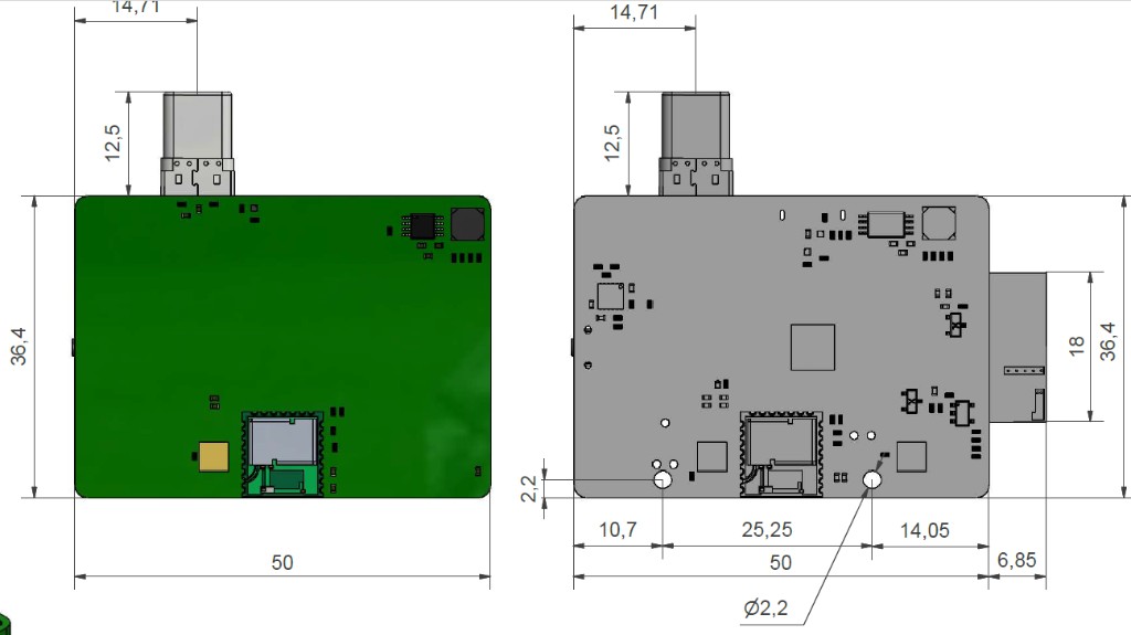
Bottom screw holes (232200–232204)
| Parameter | Value |
|---|---|
| Hole diameter | ∅2.6 mm (clearance) |
| Count / placement | Per B1 layout figure above |
Clearance for the nominated retention screw (thread major ∅2.5 mm), with margin for PCB drill tolerance and screw lead-in.
Nominated screw (self-tapping into enclosure boss — verify boss pilot with ME):
| Dimension | Value |
|---|---|
| Total length | 8 mm |
| Thread major | ∅2.5 mm |
| Thread minor | ∅1.8 mm |
| Unthreaded shank (under head) | 1 mm |
| Head diameter | ∅4.2 mm |
| Head height | 1.8 mm |
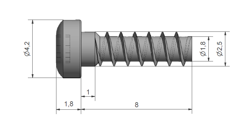
Head ∅4.2 mm is within the layout budget (head up to 5 mm OD). Part number / supplier TBD.
Scope
| Item | B1 change |
|---|---|
| 232200–232204 | Bottom mount holes ∅2.6 mm + top slots |
| 232210 | Top-edge cut-outs 1.2 × 1.92 mm on both sides (symmetric) |
| 232506 | Enclosure bosses and slot guides (separate CAD) |
| 230220 Tag | No change |
Open items
- Confirm screw part number / supplier (geometry above; head within 5 mm OD budget)
Confirm 232210 1.2 × 1.92 mm cut-outs in updated STEP— done in pcb-232210B1.step (2026-06-10); confirm Gerber matches- Update enclosure 232506 CAD in parallel with PCB
Related
- Rev B1 ECN-01 — GPIO remap — same B1 release
- Rev B1 ECN-05 — Mixed-variant panel — EMS 10-up panel for B1 qual
- 232506 Enclosure
- PCB STEP Files — Rev B1 exports incl. updated pcb-232210B1
- 232200 Base Std PCB
- Revisions Policy