Quick Start Guide
Preliminary Document
This is a preliminary guide. Product images are rendered previews. Component selection is ongoing. Content is subject to change without notice.
This guide walks you through first-time setup of your EverTag Station. The process differs slightly depending on your variant:
| Variant | Articles | Quick Start Path |
|---|---|---|
| Anchor (standard or battery) | 232010, 232011 | Step 1 → Step 2 → Step 3 → Step 4 → Step 5 |
| Gateway (WiFi or WiFi + battery) | 232012, 232013 | Step 1 → Step 2 → Step 3 → Step 4 → Step 5 → Step 6 |
Step 1 — Plug In
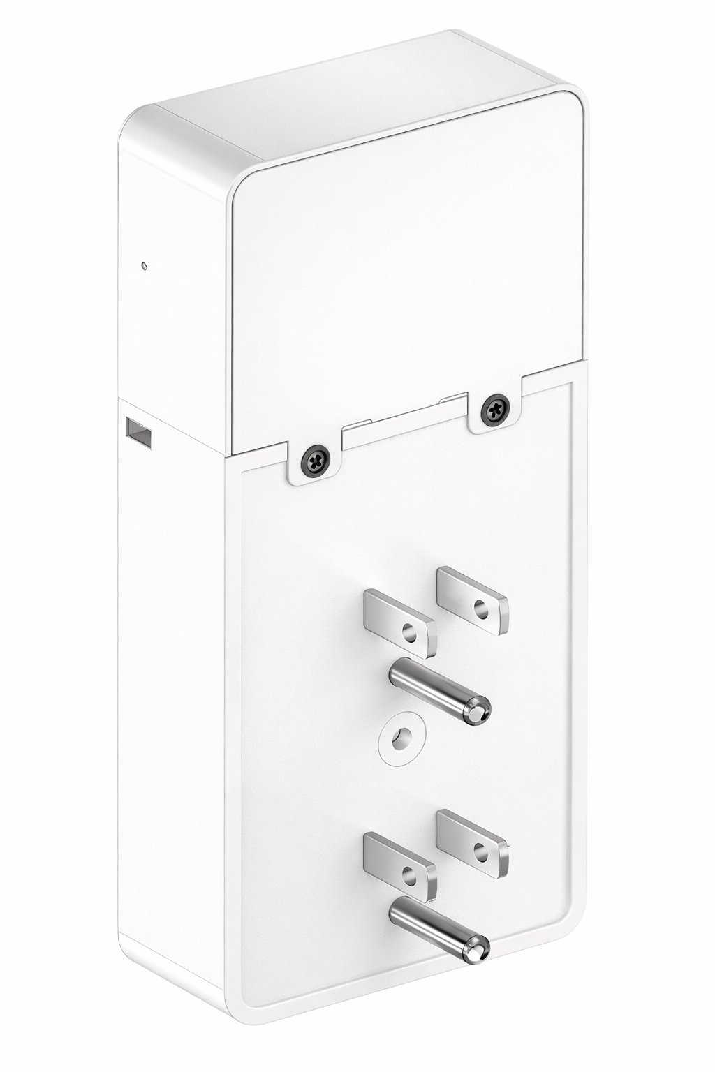
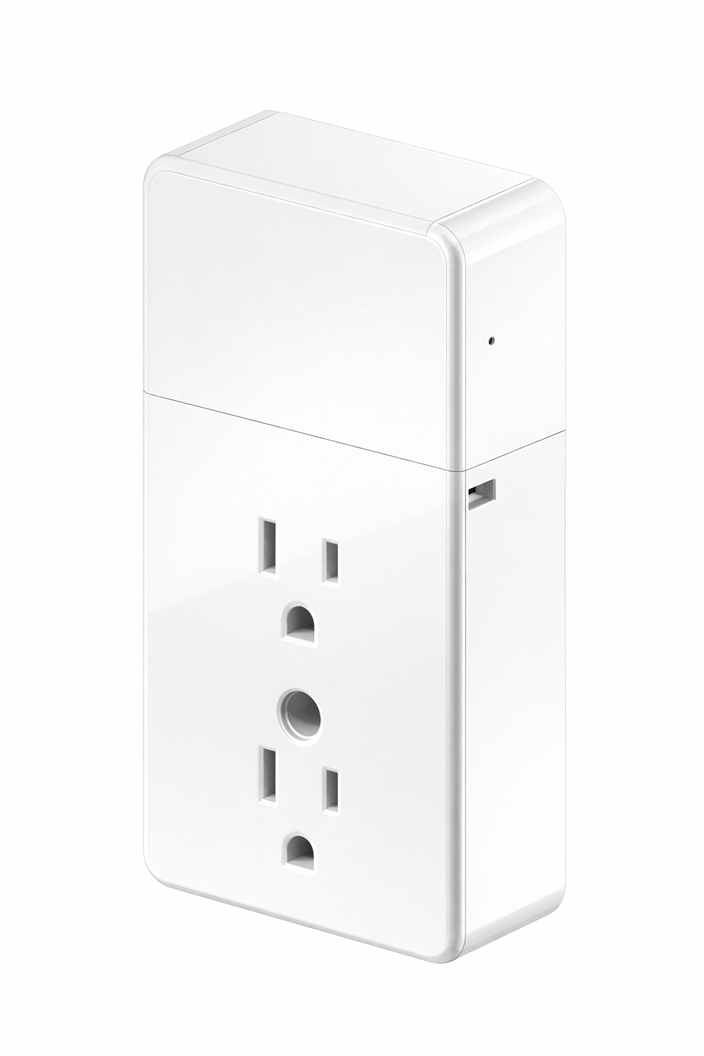
Insert the EverTag Station into a standard wall outlet with the Connectivity Module (telematics module) facing up. The Power Base Module connects directly to AC mains and provides isolated 5 V power to the Connectivity Module via USB-C.
| Feature | Location |
|---|---|
| US plug prongs | Back of Power Base Module |
| Duplex outlet (pass-through) | Front of Power Base Module — two NEMA 5-15 outlets. The Connectivity Module is powered internally via USB-C, so both outlets stay available for other devices |
| Connectivity Module | Upper housing (snaps onto the Power Base) |
The device works with both ground-prong-down and ground-prong-up wall outlet configurations (e.g. hospitals). Both pass-through outlets remain available for other devices.
Step 2 — Power On
The device is shipped in a powered-off state. After plugging in, you must activate it using one of the two methods below.
- Locate the service pinhole on the side of the enclosure.
- Insert a SIM-eject tool or paperclip into the pinhole.
- Press and hold for 5 seconds.
- The LED blinks WHITE to confirm power-on, then stays active for 5 minutes showing boot status.
- Install the CB Admin app (see Step 3).
- Open CB Admin and select the power-on command.
- Hold your phone within 2 cm of the front face of the Connectivity Module.
- CB Admin enables power via NFC.
- The LED lights up to confirm the device is powered on and stays active for 5 minutes.
| Feature | Location |
|---|---|
| Service pinhole | Side of enclosure (recessed button inside) |
| Status LED | Front face, upper area near where the two housings snap together |
| NFC tap zone | Front face, center of Connectivity Module |
LED Not Lighting Up?
Make sure you held the service button for the full 5 seconds. If the LED still does not light up, unplug the device, plug it back in, and try again.
Step 3 — Install CB Admin
Download the CB Admin app to configure your EverTag Station via NFC. The app is available for both iOS and Android.
| Platform | Link |
|---|---|
| iOS | App Store |
| Android | Google Play |
CB Admin supports NFC configuration for all EverTag Station variants — both anchors and gateways.
For more details, see the CargoBeacon Get Started guide.
NFC-Enabled Phone Required
Your phone must have NFC capability. See the Supported Phones page on the CargoBeacon website for a list of compatible devices.
Step 4 — Configure via NFC
NFC configuration works on all variants (anchor and gateway). It does not require WiFi or internet access.
Steps:
- Open CB Admin on your phone.
- Select or create a network preset with your Wirepas network settings:
- Network address
- Network channel
- Encryption key (CipherKey)
- Authentication key
- Hold your phone within 2 cm of the front face of the Connectivity Module (the upper housing).
- Tap 1 — the app writes the configuration via NFC.
- Wait for confirmation in the app (typically 1–2 seconds).
- Tap 2 (optional) — read back the device status to confirm the configuration was applied.
The device stores the configuration in flash and joins the Wirepas Mesh network automatically. Each NFC tap also activates the LED for 5 minutes, so you can immediately see the device status without pressing the service button.
Tap-and-Go Deployment
For deploying many devices, pre-configure a network preset in CB Admin. Then simply tap each device — no per-device setup needed. The LED activates on each tap, giving instant visual feedback.
For a deeper look at NFC multi-tap configuration and the TLV parameter registry, see the Configuration Guide.
Step 5 — Verify
After configuration, verify the device is operating correctly. If you just completed an NFC tap in Step 4, the LED is already active — skip to the status table below. Otherwise:
- Insert a SIM-eject tool or paperclip into the service pinhole on the side of the enclosure.
- Short-press the service button (less than 1 second).
- The LED activates for 5 minutes, showing the current system status:
| LED Color | Meaning |
|---|---|
 Green Green |
Healthy — Wirepas operational (sink connected) |
 Blue Blue |
Wirepas network joined, but no sink route yet |
 Yellow Yellow |
Powered, but not joined to a Wirepas network |
 White (breathing) White (breathing) |
Device is still booting |
 Red (blinking) Red (blinking) |
Fault — see Troubleshooting |
If the LED shows green, your anchor is online and participating in the Wirepas Mesh network. The LED turns off automatically after 5 minutes to keep the device discreet.
For anchor-only variants (232010, 232011), setup is complete.
Step 6 — Gateway: Connect to Backend
Gateway Variants Only
This step applies only to WiFi gateway variants (232012, 232013). Anchor-only variants (232010, 232011) do not need this step.
Gateway variants need an internet connection to relay Wirepas mesh data to a backend MQTT broker. You have two configuration paths:
If you already configured the device via NFC in Step 4, you can also push WiFi and MQTT settings via NFC:
- Open CB Admin and edit your network preset.
- Add WiFi settings:
- Mode: Station (joins your existing WiFi network)
- SSID and password of your site WiFi
- Band preference: 5 GHz recommended (offloads the 2.4 GHz band used by Wirepas Mesh; 2.4 GHz is supported but not recommended)
- Add MQTT broker settings:
- Broker URI (e.g.
mqtts://mqtt.cargobeacon.com) - Port (e.g.
8883) - TLS certificates (if required)
- Credentials (if required)
- Broker URI (e.g.
- Tap the device with your phone to apply.
- The gateway connects to WiFi and then to the MQTT broker automatically.
The gateway provides a built-in web interface for configuration:
- Connect to the gateway's WiFi AP:
- SSID:
ETGW-<serial>(printed on the device label) - Password:
evertag
- SSID:
- Open a browser and navigate to
http://192.168.4.1 - Log in with the default password:
evertag - Configure WiFi (Configuration → WiFi):
- Mode: Station
- Enter your site WiFi SSID and password
- Band preference: 5 GHz only or Auto
- Configure Sink (Configuration → Sink):
- Set Wirepas network address, channel, and encryption keys
- Configure MQTT (Configuration → MQTT):
- Enter broker URI, port, credentials, and TLS certificates
- Save each section.
The gateway switches to Station mode, connects to your site WiFi, and starts relaying mesh data to the MQTT broker.
After switching to Station mode, access the Web UI via the gateway's DHCP-assigned IP or http://ETGW-<serial>.local (mDNS).
For the full Web UI specification, see the Gateway Web UI Specification.
What's Next?
| Topic | Link |
|---|---|
| Detailed installation and mounting | Installation Guide |
| Full NFC and Web UI configuration reference | Configuration Guide |
| LED codes and factory reset | Troubleshooting |
| Electrical and radio specifications | Datasheet (Preliminary) |
Quick Reference
| Item | Value |
|---|---|
| Default WiFi AP SSID | ETGW-<serial> |
| Default WiFi AP password | evertag |
| Default Web UI password | evertag |
| Web UI address (AP mode) | http://192.168.4.1 |
| Web UI address (Station mode) | http://ETGW-<serial>.local |
| NFC range | < 2 cm from enclosure front |
| Service pinhole location | Side of enclosure |
| Service button hold (power-on) | 5 seconds |
| Service button hold (reboot) | ~3 seconds |
| Factory reset | Hold button while plugging in power for 10 seconds |
| LED status duration after short-press | 5 minutes |