232201 - EverTag Connectivity Module Base PCB Bat
Current revision: A2 (released 2026-04-13)
See Revision History for the full revision log.
| Article Number | 232201 |
| Name | EverTag Connectivity Module Base PCB Bat |
| Base PCB | 232200 Base Std |
| Added Feature | LiFePO4 battery backup |
| Status | Active |
Delta Document
This document describes only the differences from the 232200 Base Std. For all shared functionality (MCU, NFC, SK6812MINI LED1 system status, LED2 gateway DNP, USB-C connector, service button, TC2030 debug, PCB design notes), refer to the base PCB documentation.
1. Overview
The 232201 adds LiFePO4 battery backup to the base 232200 connectivity module. When AC power is lost, the module automatically switches to battery power, maintaining Wirepas anchor operation for a defined hold-up period. When AC power returns, the battery is recharged automatically.
Key Features (Delta from 232200)
- LiFePO4 battery (EEMB LP472040F) with JST-PHR-02 connector and 10cm cable
- Internal voltage protection circuit (over-voltage, under-voltage, overcurrent)
- Power-path management with automatic AC/battery switchover
- DC power presence detection (BSS138 level-shifter sensing 5V rail → nRF54 GPIO)
- Battery charger IC (MCP73123 -- LiFePO4 CC/CV, 3.6V cutoff)
2. Block Diagram (Delta)
graph TB
    subgraph power [Power Supply - Extended]
        VIN["5V Input from Power Base"] --> BUCK["TPS62160 Buck Converter"]
        BUCK --> RAIL["3.3V Rail"]

        VIN --> PPM["Power-Path Manager"]
        BAT["LiFePO4 Battery"] --> VPROT["Voltage Protection"]
        VPROT --> PPM
        PPM --> BUCK

        PPM --> CHRG["MCP73123 Charger"]
        CHRG --> VPROT
    end

    subgraph mcu_block [MCU / Radio Module]
        PAN611["PAN611 - nRF54L15"]
    end

    RAIL --> PAN611

    PAN611 -.->|"Battery presence"| PPM
    PAN611 -.->|"Battery voltage ADC"| BAT
Power-Path Operation
| AC Power | Battery | Mode |
|---|---|---|
| Present | Absent | Direct 5V to regulator |
| Present | Present | 5V powers system + charges battery |
| Lost | Present | Battery powers system through protection circuit |
| Lost | Absent | System off |
3. Schematics (Delta)
3.1 Battery Circuit
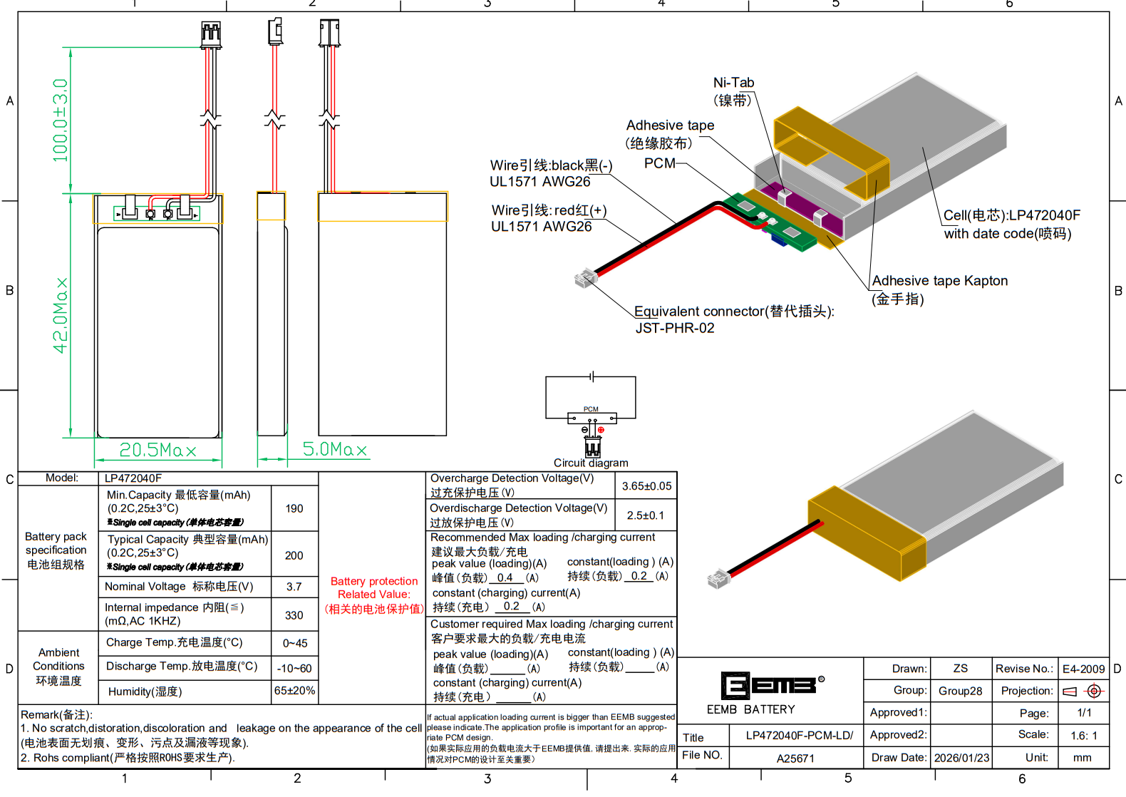
Battery (Article 232250)
| Parameter | Value |
|---|---|
| Cell | EEMB LP472040F-PCM-LD |
| Chemistry | LiFePO4 (Lithium Iron Phosphate) |
| Nominal Voltage | 3.2V |
| Capacity | 330 mAh (typical, 0.2C @ 25C) |
| Connector | JST-PHR-02 |
| Cable Length | 10cm |
| Article Number | 232250 |
Voltage Protection Circuit
An internal voltage protection circuit protects the battery from:
- Over-voltage -- Prevents charging above safe limit
- Under-voltage -- Disconnects load at minimum cell voltage
- Overcurrent -- Protects against short circuit
| Parameter | Value |
|---|---|
| Protection IC | Integrated in battery PCM (LP472040F-PCM-LD) |
| Additional board-level protection | MCP73123 OVP (6.5V input), reverse discharge |
Charger IC -- MCP73123
| Parameter | Value |
|---|---|
| IC | Microchip MCP73123-22SI/MF |
| Charge Voltage | 3.6V (factory preset for LiFePO4) |
| Charge Current | Programmable via R_PROG: 130 mA to 1100 mA |
| Recommended I_charge | 250 mA (0.5C for ~500 mAh cell, safe and fast enough) |
| R_PROG for 250 mA | 4.0k (1%) |
| Input Voltage | 4.15V -- 6.5V (OVP at 6.5V) |
| Input Source | 5V from Power Base Module |
| End-of-Charge | 10% of I_charge (25 mA) |
| Safety Timer | 4 hours (configurable: 4/6/8 HR or disabled) |
| Voltage Accuracy | ± 0.5% |
| Package | 10-pin DFN (3 mm x 3 mm) |
| Quiescent Current | < 75 uA (standby, battery full) |
| Operating Temperature | -40 to +85 C |
| Est. Price | ~$1.50 @ 10k |
Charge profile: Constant Current (CC) at 250 mA until battery reaches 3.6V, then Constant Voltage (CV) at 3.6V until current drops to 25 mA (end-of-charge). The MCP73123 includes integrated reverse discharge protection, thermal regulation (junction temperature limiting), and automatic recharge at 95% of charge voltage.
graph LR
    VIN_5V["5V Input"] --> C_IN["C_IN: 4.7uF"]
    C_IN --> MCP["MCP73123"]
    MCP -->|"VBAT"| C_OUT["C_OUT: 4.7uF"]
    C_OUT --> BAT_CONN["JST S2B-PH"]

    MCP ---|"PROG pin"| R_PROG["R_PROG: 4.0k 1%"]
    R_PROG --> GND1["GND"]

    MCP -->|"STAT"| MCU_STAT["nRF54 GPIO: CHARGE_STATUS"]
Charge Current Programming
The charge current is set by a single resistor on the PROG pin:
| R_PROG (1%) | Charge Current | Use Case |
|---|---|---|
| 10k | 100 mA | Slow charge, minimal heat |
| 4.0k | 250 mA | Recommended -- 0.5C for LP472040F |
| 2.0k | 500 mA | Fast charge, more heat |
| 1.0k | 1000 mA | Maximum rate (verify thermal) |
Formula: I_charge = 1000V / R_PROG (where 1000V is the MCP73123 internal reference constant).
Status Pin
The MCP73123-22SI/MF has a single STAT output (pin 7, open-drain). LOW = charging in progress; HIGH-Z = charge complete, standby, or fault.
| Pin | MCP73123 Pin | Direction | nRF54 GPIO | Function |
|---|---|---|---|---|
| STAT | Pin 7 | Output (open-drain) | P2.04 (CHARGE_STATUS) | LOW = charging; HIGH-Z = not charging |
MCP73123 Pinout
The MCP73123-22SI/MF (10-pin DFN) has only one status output (STAT, pin 7). Pins 1--2 are VDD, pins 3--4 are VBAT, pin 10 is PROG, pins 8--9 are VSS. There is no PG (Power Good) or second status pin on this IC.
Low-Cost Alternative: CN3058E
For cost-sensitive Asian production, the Consonance CN3058E ($0.13 @ 4k on LCSC, SOP-8 package) is a pin-compatible-in-function LiFePO4 charger with similar features (1A max, 3.6V cutoff, status output). However, the MCP73123 is preferred for Western production due to Microchip's long-term availability commitment and tighter voltage accuracy (± 0.5% vs ± 1.5%).
Thermal Considerations
- At 250 mA charge current from 5V input to 3.2V battery: power dissipation = (5.0 - 3.2) x 0.25 = 0.45W
- MCP73123 has internal thermal regulation -- it reduces charge current automatically if junction temperature exceeds 100C
- Ensure adequate copper pour under the DFN pad (thermal pad) for heat sinking
- At 0.45W, no external heatsink is needed in the enclosed design
Power-Path Management
The power-path circuit uses a simple ideal diode OR topology with the MCP73123 managing the charge path:
| Parameter | Value |
|---|---|
| Function | Automatic switchover between AC (5V) and battery (3.2V) |
| AC present | 5V powers TPS62160 directly; MCP73123 charges battery |
| AC lost | Battery 3.2V feeds TPS62160 via Schottky/ideal diode |
| DC detection | BSS138 MOSFET sensing 5V rail (LOW = DC present) to nRF54 GPIO |
graph LR
    VIN["5V AC"] -->|"Main path"| DIODE_AC["Ideal Diode / Schottky"]
    DIODE_AC --> V_SYS["V_SYS → TPS62160"]

    VIN --> MCP["MCP73123"]
    MCP -->|"VBAT"| BAT["Battery 3.2V"]

    BAT -->|"Backup path"| DIODE_BAT["Ideal Diode / Schottky"]
    DIODE_BAT --> V_SYS
TPS62160 Input Range
The TPS62160 operates from 3V to 17V input, so it works directly from either 5V (AC) or 3.2V (battery). At 3.2V input with 3.3V output (set by R1/R2 feedback divider), the converter operates in near-100% duty cycle mode. Verify that the 3.3V output regulates correctly with only 3.2V input -- there may be minimal dropout. If not, adjust the feedback divider for a 3.0V output rail or use an LDO bypass for battery mode.
3.2 Battery Connector
| Parameter | Value |
|---|---|
| PCB Header | JST S2B-PH-SM4-TB(LF)(SN) -- 2-pin SMT, top-entry |
| Pitch | 2.0 mm |
| Pin 1 | Battery + (via protection circuit) |
| Pin 2 | GND |
| Mating Connector | JST PHR-02 (on battery cable, 10 cm) |
| Mating Contact | JST SPH-002T-P0.5L (crimp terminal) |
| Current Rating | 2A per contact |
| Est. Price (header) | ~$0.10 @ 10k |
JST PH Series
The JST PH series (2.0 mm pitch) is the de-facto standard for small battery connections in IoT devices. The S2B-PH-SM4-TB is the SMT variant with horizontal (top-entry) orientation, compatible with reflow soldering. The battery cable uses the mating PHR-02 housing with SPH crimp contacts -- this is the same connector system used by EEMB on the LP472040F battery.
4. Pin-Out (Delta)
Additional GPIO requirements beyond 232200 base pin-out:
| GPIO | Function | Direction | Notes |
|---|---|---|---|
| P2.03 | DC_PRESENT | Input | BSS138 level-shifter sensing 5V rail (100k pull-up). LOW = DC present |
| P1.06 | BAT_VOLTAGE | ADC Input | Battery voltage via resistor divider (SAADC AIN2) |
| P2.04 | CHARGE_STATUS | Input | MCP73123 STAT pin 7 (open-drain, 10k pull-up). LOW = charging |
| P2.05 | CHARGE_ENABLE | Output | Enable/disable charging (MCP73123 CE or power-path FET) |
Charger State Machine
Three battery GPIO signals plus BAT_VOLTAGE ADC provide charger state visibility:
| CHARGE_STATUS (STAT) | DC_PRESENT | BAT_VOLTAGE | State |
|---|---|---|---|
| LOW | LOW | rising | Charging in progress |
| HIGH | LOW | > 3.4V | Charge complete |
| HIGH | LOW | < 2.5V | Standby (no battery or idle) |
| HIGH | HIGH | > 2.5V | Running on battery |
| HIGH | HIGH | < 1.0V | No power source |
Fault detection: if CHARGE_STATUS stays LOW for longer than the MCP73123 safety timer (4 hours), firmware should flag a charge fault (timeout-based, since the MCP73123 has only one STAT output and cannot signal faults via a separate pin).
GPIO Reserve
P1.03 is available as GPIO reserve on non-sensor battery variants (232201). On 232204, P1.03 is assigned to RADAR_EN (A121 sensor enable). P1.02 remains as GPIO reserve on all variants. BAT_VOLTAGE uses P1.06 (AIN2) -- a true SAADC-capable pin in the always-configured table.
5. Component Selection (Delta)
5.1 Battery
| Parameter | Value |
|---|---|
| Manufacturer | EEMB |
| Part Number | LP472040F-PCM-LD |
| Chemistry | LiFePO4 (Lithium Iron Phosphate) |
| Nominal Voltage | 3.2V |
| Article | 232250 |
| Connector | JST-PHR-02 |
| Cable Length | 10cm |
| Est. Price | ~3--4 USD @ 5k volume |
Rationale:
- Thermal stability -- LiFePO4 is inherently safer than Li-ion/LiPo, reducing fire risk in permanently installed wall-powered devices
- Long calendar life -- low self-discharge, 10+ year operation target
- Logistics -- LiFePO4 cells are exempt from UN3480 hazardous goods classification, simplifying shipping
- Lower fire risk -- critical for devices permanently mounted in occupied buildings
5.2 JST Connector (PCB Header)
| Parameter | Value |
|---|---|
| Manufacturer | JST |
| Part Number | S2B-PH-SM4-TB(LF)(SN) |
| Series | PH (2.0 mm pitch) |
| Positions | 2 |
| Mount | SMT, top-entry (horizontal) |
| Current | 2A per contact |
| Est. Price | ~$0.10 @ 10k |
Rationale: Industry-standard battery connector, reflow-compatible, mates directly with EEMB battery cable. Available from DigiKey, Mouser, and LCSC.
Supplier Links:
| Source | Part Number | Notes |
|---|---|---|
| DigiKey | 455-1749-1-ND | Western |
| Mouser | JST S2B-PH-SM4-TB | Western |
| LCSC | C160352 | Low-cost |
5.3 Charger IC -- MCP73123
| Parameter | Value |
|---|---|
| Manufacturer | Microchip Technology |
| Part Number | MCP73123-22SI/MF |
| Chemistry | LiFePO4 (3.6V charge voltage) |
| Max Current | 1100 mA (programmable via R_PROG) |
| Package | 10-pin DFN (3 x 3 mm) |
| Features | OVP, thermal regulation, safety timer, auto-recharge |
| Est. Price | ~$1.50 @ 10k |
Rationale:
- LiFePO4-specific -- Factory-set 3.6V charge voltage, no resistor programming for voltage
- Programmable current -- Single resistor sets charge current (250 mA recommended)
- Tight accuracy -- ± 0.5% voltage regulation through -5 to +55C
- Small footprint -- 3 x 3 mm DFN, suitable for space-constrained PCB
- Integrated protections -- OVP (6.5V), reverse discharge, thermal regulation, safety timer
- Long availability -- Microchip product with active status, broad distribution
Supplier Links:
| Source | Part Number | Notes |
|---|---|---|
| DigiKey | MCP73123-22SI/MF-ND | Western |
| Mouser | MCP73123-22SI/MF | Western |
| Octopart | Search | Price comparison |
Low-Cost Alternative: Consonance CN3058E (SOP-8, ~$0.13 @ 4k on LCSC C112011). Functionally similar but lower voltage accuracy (± 1.5%) and Consonance is a smaller manufacturer. Use for cost-optimized Asian production runs.
6. PCB Design Notes (Delta)
- Battery connector placement: accessible for assembly, cable routing clear of RF area
- Power-path management circuit: close to both 5V input and battery connector
- Battery voltage sense trace: Kelvin connection to connector pin, route away from switching regulator
- Additional area required vs. 232200: charger IC + power-path components
For base PCB design notes, see 232200 PCB Design Notes.
7. Test Points (Delta)
Additional test points beyond 232200 test points:
| TP # | Signal | Expected Value | Notes |
|---|---|---|---|
| TP10 | BAT+ | ~3.2V (nominal) | Battery positive (after protection) |
| TP11 | MCP_VBAT | 3.2--3.6V | MCP73123 VBAT output (charge voltage) |
| TP12 | MCP_PROG | ~1.0V (chg) | MCP73123 PROG pin (I_charge = 1000/R_PROG) |
| TP13 | V_SYS | 3.2--5.0V | System rail after diode OR (to TPS62160) |
Battery-Specific Tests
- Battery connector polarity verification (Pin 1 = BAT+, Pin 2 = GND)
- MCP73123 VBAT output: 3.6V ± 0.5% when charging (measure at TP11)
- Charge current: ~250 mA during CC phase (measure at TP12: V_PROG ~1.0V)
- STAT pin (pin 7): low during charging, high-Z when complete
- DC_PRESENT (BSS138 circuit): LOW when 5V present, HIGH when absent
- DC presence detection (nRF54 GPIO reads correct state)
- AC power present -> verify battery charging begins (CHARGE_STATUS = low)
- AC power removed -> verify V_SYS switches to battery (~3.2V at TP13)
- AC power restored -> verify system switches back and charging resumes
- Battery voltage ADC reads within expected range (3.0--3.6V)
- Thermal regulation: verify MCP73123 reduces current at elevated temperature
- Safety timer: verify charge terminates after 4 hours if battery is faulty
- Under-voltage protection: verify system shutdown at minimum cell voltage (~2.0V)
8. Revision History
See Revisions for the full per-revision log, release artifacts, and known limitations.
Related Documents
- 232200 Base Std -- Base PCB (all shared functionality)
- 232203 Base Bat+WIFI -- Combined battery + WiFi variant
- Sales Articles -- Products using this PCB: 232002 (EU), 232011 (US)