EverTag Station (nRF54)
| Product Family | EverTag Station |
| MCU Module | Panasonic PAN611 (nRF54L15) |
| Power | Wall-powered (5V from Power Base Module) |
| Application | Wirepas Mesh anchor, WiFi gateway, NFC configuration |
| PCB Article Range | 232200--232211 |
Overview
The EverTag Station is a modular wall-powered Wirepas anchor and gateway platform designed for EU and US markets. The system is architected around strict separation between:
- AC Safety Domain -- Power Base Module (isolated AC-DC, Class 2 output)
- Class 2 Low-Voltage Domain -- Connectivity Module (nRF54 + optional WiFi/battery/LTE)
The platform supports Wirepas anchor functionality, optional WiFi gateway, optional LiFePO4 battery backup, and is prepared for future LTE modem extension and PIR/Radar sensing.
Design Philosophy
- Strict AC/LV separation -- only Power Base under safety listing, allowing unlimited telematics SKU expansion without new safety certification
- Modular certification -- pre-certified radio modules (PAN611, ESP32-C5) reduce regulatory risk
- Long product lifetime -- components selected for >10 year availability
- Low BOM risk -- minimum 2 global distributors per component, no EOL-risk families
- Scalable manufacturing -- EMS manufacturing in Asia (primary) and Europe (secondary)
Enclosure
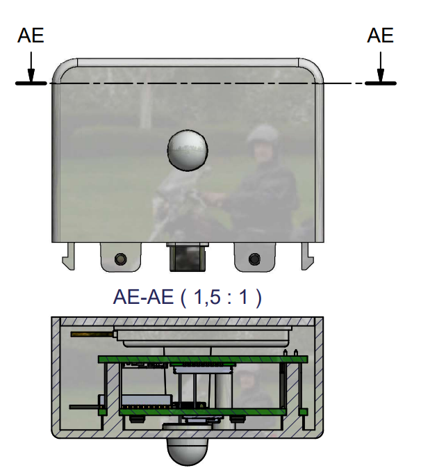
The EverTag Station is built from two separate housings that snap together: the Power Base Module (lower housing — the isolated AC-DC USB charger, article 232507) and the Connectivity Module (upper housing, enclosure 232506). Both enclosures are produced by the same supplier, who also delivers the complete charger electronics.
Shared Enclosure
The enclosure (232506) is shared across all connectivity module variants. The PCB is not centered inside the enclosure. LED and button placement on the PCB must account for the off-center position to align with the enclosure window and access points.
Documentation
-
Sales Articles & Subassemblies
Complete product articles (232001-232013), subassemblies (232500-232507), and article-to-PCB mapping.
-
PCB Articles
Detailed hardware documentation per PCB: schematics, pin-outs, component selection, and design notes.
Design proposals (draft)
| ECN | Proposal | Scope |
|---|---|---|
| ECN-01 | Rev B1 ECN-01 — GPIO remap | nRF54L15 pin changes — all Station boards + shared with Tag |
| ECN-02 | Rev B1 ECN-02 — Enclosure mounting | Screw mount + daughter-board slots — Station only |
| ECN-03 | Rev B1 ECN-03 — PAN611 keep-out | Shrink module antenna zone — 232200–232204 only |
| ECN-05 | Rev B1 ECN-05 — Mixed-variant panel | One 10-up EMS panel (2× each 232200–232204) — Station only |
| ECN-06 | Rev B1 ECN-06 — LTE SIM7672G | Single global LTE module on 232210 + 232211 — drop-in BOM |
| ECN-08 | Rev B1 ECN-08 — PAN611 stepped footprint | U1 pads outside silkscreen — 232200–232204 only |
| ECN-10 | Rev B1 ECN-10 — Silkscreen article / revision | Fix variant silk legends on 232202, 232203 — Station only |
| ECN-11 | Rev B1 ECN-11 — NFC antenna top side | Move NFC coil to L1 (PAN611 side) — 232200–232204 |
| ECN-12 | Rev B1 ECN-12 — Battery connector rotation | Rotate JST header 180° — cable over PCB — 232201/232203/232204 |
See also Revisions Policy.
PCB Quick Links
| PCB | Name | Key Components | Status |
|---|---|---|---|
| 232200 | Base Std | PAN611 (nRF54L15) + NFC | Active |
| 232201 | Base Bat | + LiFePO4 battery (EEMB LP472040F) | Active |
| 232202 | Base WIFI | + ESP32-C5 WROOM WiFi gateway | Active |
| 232203 | Base Bat+WIFI | + Battery + WiFi combined | Active |
| 232204 | Base Bat+Radar | + PIR/Radar sensor (anchor, no WiFi/LTE) | Not in first iteration |
| 232210 | Ext LTE EU | SIMCom SIM7672E LTE Cat-1bis modem | Not in first iteration |
| 232211 | Ext LTE US | SIMCom SIM7672NA LTE Cat-1bis modem | Not in first iteration |
Firmware
The Station family uses two firmware builds:
| Build | Boards | Application |
|---|---|---|
| Tag/Anchor | 232200, 232201 | Wirepas anchor, NFC config (shared with EverTag Tag nRF54) |
| Gateway | 232202, 232203, 232204 | Wirepas gateway + ESP32 WiFi control |
Board variant is detected at runtime via resistor divider on ADC pin P1.07. See Firmware Compatibility for the full matrix.