Installation Guide
Preliminary Document
This is a preliminary guide. Product images are rendered previews. Component selection is ongoing. Content is subject to change without notice.
Package Contents
| Item | Quantity | Notes |
|---|---|---|
| EverTag Station (assembled) | 1 | Power Base + Connectivity Module in enclosure |
| Quick Start card | 1 | QR code linking to this guide |
Product Overview
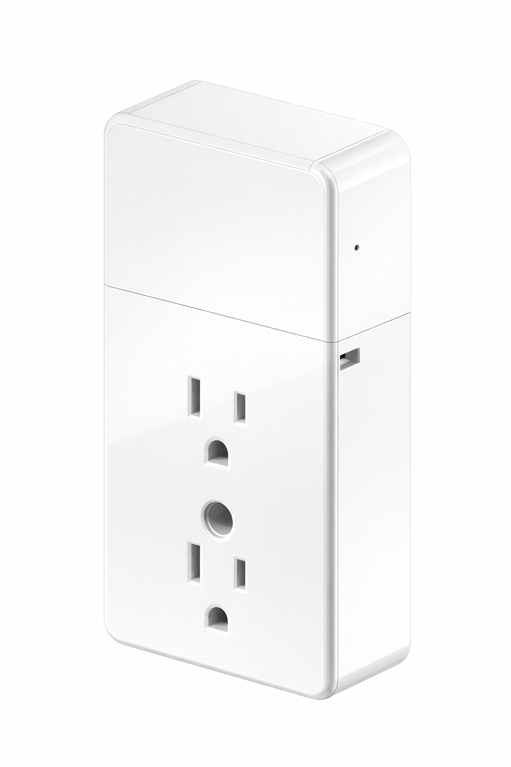
Front View
| # | Feature | Description |
|---|---|---|
| A | Duplex pass-through outlet | Two standard US (NEMA 5-15) outlets on the Power Base Module. The Connectivity Module is powered internally via USB-C, so both outlets remain available for other devices. The device works in both ground-prong-down and ground-prong-up installations. |
| B | Connectivity Module | Upper housing — a separate enclosure that snaps onto the Power Base. Contains the nRF54 radio, NFC antenna, and optional WiFi/battery subsystems. |
| C | Status LED | Addressable RGB LED near the top of the Connectivity Module. Indicates system health when activated. |
| D | Housing join | The Power Base Module (lower housing) and Connectivity Module (upper housing) are two separate enclosures that snap together here. |
| E | Service pinhole (side) | Located on the side of the enclosure. Recessed button accessible with a SIM-eject tool or paperclip. Used for power-on (5 s hold), status check (short press), reboot (~3 s hold), and factory reset (hold while plugging in for 10 s). |
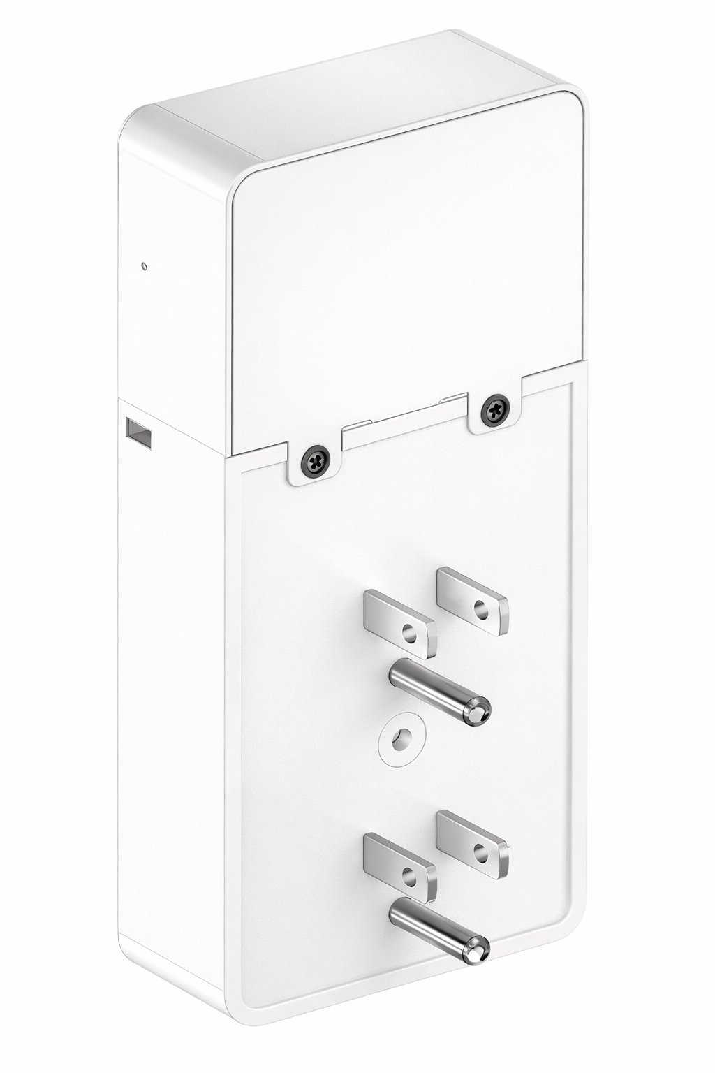
Back View
| # | Feature | Description |
|---|---|---|
| F | US plug prongs | Three-prong US plug (NEMA 5-15P) on the Power Base Module. |
| G | Enclosure clips | Hold the enclosure halves together. |
Top View
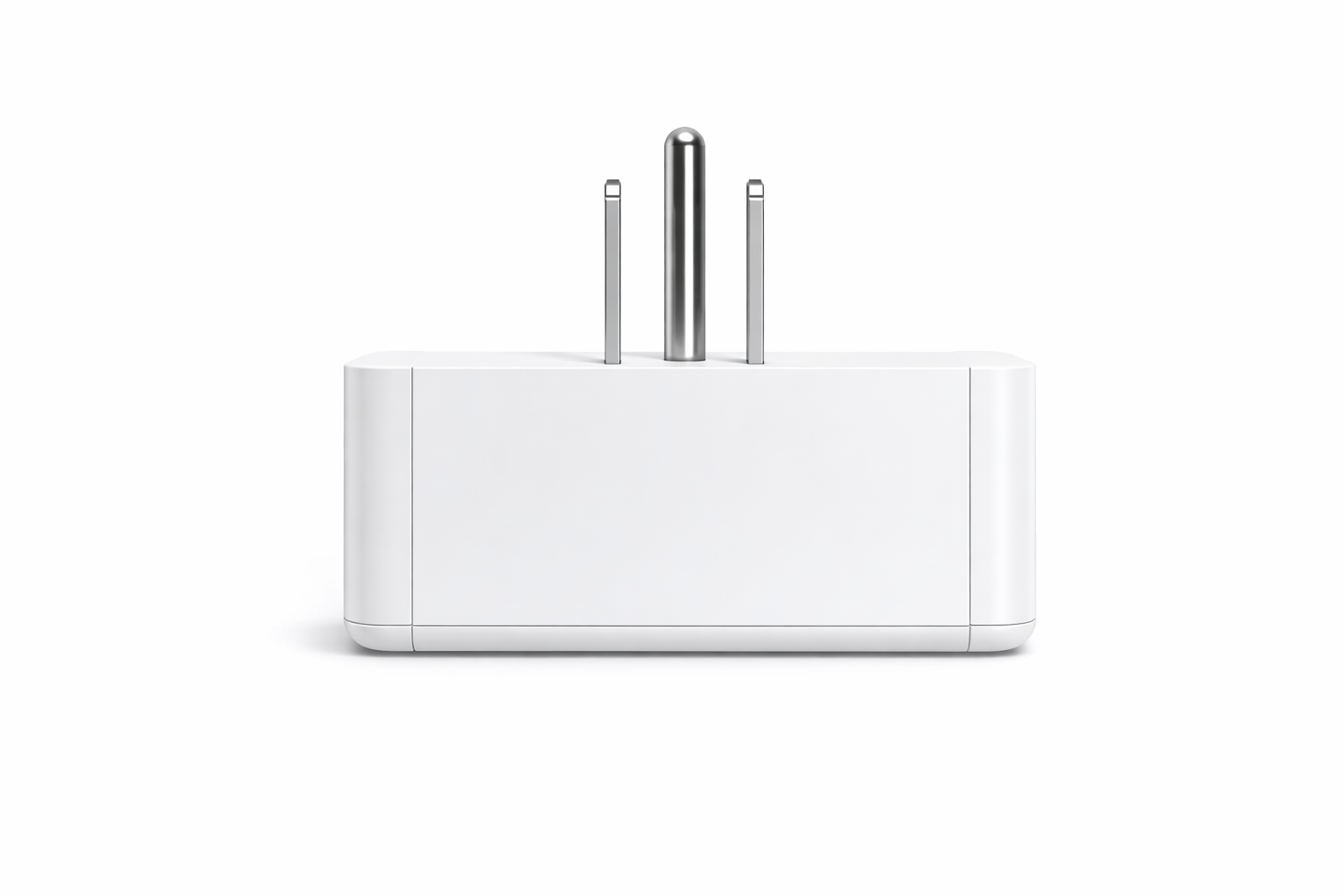
The compact profile allows the device to sit flat against the wall without protruding significantly.
Installation
- Insert the EverTag Station directly into a standard wall outlet.
- Power on the device using the service button (5-second hold via the pinhole on the side) or via NFC using CB Admin. See Quick Start — Step 2 for details.
- Proceed to Quick Start — Step 3 for configuration.
The Connectivity Module is powered internally via USB-C, so both pass-through outlets remain available for other devices. The device supports both ground-prong-down and ground-prong-up wall outlet configurations.
Orientation
Always install with the Connectivity Module (telematics module) facing up. The device supports wall outlets with the ground prong either up or down.
Consistent Height
For best positioning accuracy, install all anchors at the same height across the installation. Use outlets at a consistent elevation whenever possible. Avoid placing directly behind large metal objects or inside metal enclosures.
Placement Guidelines
Wirepas Mesh Coverage
The EverTag Station acts as a fixed anchor in the Wirepas Mesh network. Placement affects positioning accuracy and network reliability.
| Guideline | Recommendation |
|---|---|
| Height | Install all anchors at the same height across the installation for best positioning accuracy |
| Spacing | 15–30 m between anchors (indoor, line-of-sight) |
| Avoid | Metal enclosures, behind thick concrete walls, near high-power RF sources |
| Minimum anchors | 3 anchors for 2D positioning |
| Orientation | Front face (NFC antenna side) should face the coverage area |
WiFi Gateway Placement (232012, 232013)
Gateway variants additionally need WiFi connectivity to your site network. Consider:
| Guideline | Recommendation |
|---|---|
| WiFi signal | Place within range of your site WiFi access point |
| Band preference | Use 5 GHz WiFi when available. This offloads the 2.4 GHz band used by Wirepas Mesh, improving both WiFi and mesh performance. 2.4 GHz WiFi is supported but not recommended. |
| Line of sight | Prefer line-of-sight to the WiFi access point when possible |
Environmental Requirements
| Parameter | Range | Notes |
|---|---|---|
| Operating temperature | −20 °C to +60 °C | Non-condensing humidity |
| Storage temperature | −40 °C to +85 °C | |
| Indoor / Outdoor | Indoor only | Enclosure is not IP-rated for outdoor use |
| Input voltage (from outlet) | 120 V AC, 60 Hz | US only (Power Base Module) |
Safety
Do not open the enclosure. There are no user-serviceable parts inside. The Power Base Module contains AC mains voltages. See Safety & Regulatory.