PCB Articles
This section contains the hardware architecture documentation for each PCB assembly in the EverTag Connectivity Module family. The 232200 Base Std is the main reference document; variant PCBs describe only the differences from the base.
PCB Comparison
| PCB | Name | MCU Module | WiFi | Battery | NFC | PIR | LTE Ext | Status |
|---|---|---|---|---|---|---|---|---|
| 232200 | Base Std | PAN611 (nRF54L15) | - | - | PCB antenna | - | - | Active |
| 232201 | Base Bat | PAN611 (nRF54L15) | - | LiFePO4 | PCB antenna | - | - | Active |
| 232202 | Base WIFI | PAN611 (nRF54L15) | ESP32-C5 | - | PCB antenna | - | - | Active |
| 232203 | Base Bat+WIFI | PAN611 (nRF54L15) | ESP32-C5 | LiFePO4 | PCB antenna | - | - | Active |
| 232204 | Base Bat+Radar | PAN611 (nRF54L15) | - | LiFePO4 | PCB antenna | Yes | - | Not in first iteration |
| 232210 | Ext LTE EU | - | - | - | - | - | SIM7672E | Not in first iteration |
| 232211 | Ext LTE US | - | - | - | - | - | SIM7672NA | Not in first iteration |
Document Structure
The base PCB (232200) document contains all chapters in full detail:
- Overview
- Block Diagram
- Schematics
- Pin-Out (incl. GPIO assignments for firmware)
- Component Selection
- PCB Design Notes
- Test Points & Validation
- Revision History
Variant PCBs (232201-232203) document only the delta from the base. For shared functionality, they reference the 232200 documentation.
Future PCBs (232204, 232210, 232211) are fully specified but are not included in the first PCB iteration. The enclosure and base platform are prepared for these extensions.
graph TD
    Base["232200 Base Std - Full Document"]
    Bat["232201 Base Bat - Battery delta"]
    Wifi["232202 Base WIFI - WiFi delta"]
    BatWifi["232203 Base Bat+WIFI - Combined delta"]
    BatRadar["232204 Base Bat+Radar - Anchor with presence"]
    LteEu["232210 Ext LTE EU - Future"]
    LteUs["232211 Ext LTE US - Future"]

    Base --> Bat
    Base --> Wifi
    Base --> BatWifi
    Base --> BatRadar
    BatWifi --> LteEu
    BatWifi --> LteUs
Board Variant Detection (HW Design)
All assembly variants use a resistor divider on P1.07 (V_SAMPLE) for firmware to detect the board type at runtime. Populate R_bottom per assembly variant — R_top is fixed at 100k (1%).
| Assembly Variant | R_top | R_bottom | Notes |
|---|---|---|---|
| 232200 Base Std | 100k | 16.5k | |
| 232201 Base Bat | 100k | 33k | |
| 232202 Base WiFi | 100k | 49.9k | |
| 232203 Base Bat+WiFi | 100k | 66.5k | |
| 232204 Base Bat+Radar | 100k | 82.5k |
Extension boards (via P1.12 EXT_DETECT):
| Extension | R_top | R_bottom |
|---|---|---|
| 232210 Ext LTE EU | 100k | 16.5k |
| 232211 Ext LTE US | 100k | 33k |
Circuit & Tolerance
VCC → R_top (100k 1%) → P1.07 (ADC) → R_bottom (variant) → GND. Use 1% resistors. Full scheme, ADC windows, and tolerance analysis: Firmware Compatibility — Board Variant Detection.
Shared Enclosure
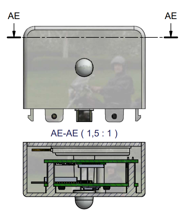
All connectivity module variants share the same enclosure (article 232506):
| Parameter | Value |
|---|---|
| Material | Flame-retardant PC (Loton 5420HE, halogen-free) |
| Flame rating | UL94 V-0 @ 1.5 mm |
| Color | White matte |
| Prepared features | PIR window region (not populated), internal volume for extension board (LTE modem + on-board chip antenna) |
PCB Placement
The PCB is not centered inside the enclosure. LED and button placement on the PCB must account for the off-center position to align with the enclosure window and access points. Complete enclosure drawings are provided separately to the PCB designer (outside the scope of this documentation).